


| Appearance | Sensing distance | Output configuration | Operation mode: NO | Operation mode: NC | |
| M12 | 3 mm | DC 2-wire (polarity) | E2EH-X3D1 2M | E2EH-X3D2 2M | |
| DC 2-wire (no polarity) * | E2EH-X3D1-T 2M | --- | |||
| DC 3-wire (PNP) | E2EH-X3B1 2M | E2EH-X3B2 2M | |||
| DC 3-wire (NPN) | E2EH-X3C1 2M | E2EH-X3C2 2M | |||
| M18 | 7 mm | DC 2-wire (polarity) | E2EH-X7D1 2M | E2EH-X7D2 2M | |
| DC 2-wire (no polarity) * | E2EH-X7D1-T 2M | --- | |||
| DC 3-wire (PNP) | E2EH-X7B1 2M | E2EH-X7B2 2M | |||
| DC 3-wire (NPN) | E2EH-X7C1 2M | E2EH-X7C2 2M | |||
| M30 | 12 mm | DC 2-wire (polarity) | E2EH-X12D1 2M | E2EH-X12D2 2M | |
| DC 2-wire (no polarity) * | E2EH-X12D1-T 2M | --- | |||
| DC 3-wire (PNP) | E2EH-X12B1 2M | E2EH-X12B2 2M | |||
| DC 3-wire (NPN) | E2EH-X12C1 2M | E2EH-X12C2 2M | |||
| Appearance | Sensing distance | Output configuration | Operation mode: NO | Operation mode: NC | |
| M12 | 3 mm | DC 2-wire (polarity) | E2EH-X3D1-M1G | E2EH-X3D2-M1G | |
| DC 3-wire (PNP) | E2EH-X3B1-M1 | E2EH-X3B2-M1 | |||
| DC 3-wire (NPN) | E2EH-X3C1-M1 | E2EH-X3C2-M1 | |||
| M18 | 7 mm | DC 2-wire (polarity) | E2EH-X7D1-M1G | E2EH-X7D2-M1G | |
| DC 3-wire (PNP) | E2EH-X7B1-M1 | E2EH-X7B2-M1 | |||
| DC 3-wire (NPN) | E2EH-X7C1-M1 | E2EH-X7C2-M1 | |||
| M30 | 12 mm | DC 2-wire (polarity) | E2EH-X12D1-M1G | E2EH-X12D2-M1G | |
| DC 3-wire (PNP) | E2EH-X12B1-M1 | E2EH-X12B2-M1 | |||
| DC 3-wire (NPN) | E2EH-X12C1-M1 | E2EH-X12C2-M1 | |||
Appearance |
Cable length | Sensor I/O Connector model | Applicable Proximity Sensors | |
| Straight | 2 m | XS2F-E421-D80-E | E2EH-X[]D[]-M1G E2EH-X[]B[]-M1 E2EH-X[]C[]-M1 |
|
| 5 m | XS2F-E421-G80-E | |||
| L-shape | 2 m | XS2F-E422-D80-E | ||
| 5 m | XS2F-E422-G80-E | |||
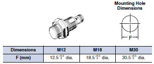
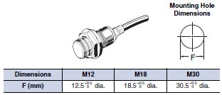
| Size Shielded Model |
M12 | M18 | M30 | |
| Shielded | ||||
| E2EH-X3D[] | E2EH-X7D[] | E2EH-X12D[] | ||
| Sensing distance | 3 mm | 7 mm | 12 mm | |
| Set distance *1 | 0 to 2.4 mm | 0 to 5.6 mm | 0 to 9.6 mm | |
| Differential travel | 15% max. of sensing distance | |||
| Detectable object | Ferrous metal (The sensing distance decreases with non-ferrous metal. Refer to Datasheet.) | |||
| Standard sensing object | Iron, 12 × 12 × 1 mm | Iron 21 × 21 × 1 mm | Iron 36 × 36 × 1 mm | |
| Response frequency *2 | 500 Hz | 300 Hz | 100 Hz | |
| Power supply voltage (operating voltage range) |
12 to 24 VDC, ripple (p-p): 10% max. (10 to 32 VDC, however, 24 VDC max. at temperatures over 100 ° C) |
|||
| Leakage current | 0.8 mA max. | |||
| Control output |
Load current |
3 to 100 mA (however, 3 to 50 mA at 100 to 110 ° C) | ||
| Residual voltage *3 |
Polarity Models: 3 V max. No polarity Models: E2EH-X[]D[]-T : (5 V max. *3 (Load current: 100 mA, Cable length 2 m) |
|||
| Indicators | D1 Models: Operation indicator (red), Setting indicator (yellow) D2 Models: Operation indicator (yellow) |
|||
| Operation mode (with sensing object approaching) |
D1 Models: NO D2 Models: NC Refer to Datasheet. |
|||
| Protection circuits | Surge suppressor, Load short-circuit protection | |||
| Ambient temperature range |
Operating: 0 to 100 ° C (0 to 110 ° C 1,000 h) *4 Storage: - 25 to 70 ° (with no icing or condensation) |
|||
| Ambient humidity range | 35% to 95% | |||
| Temperature influence | ± 10% max. of sensing distance at 23 ° C in the temperature range of 0 to 70 ° C. ± 15% max. of sensing distance at 23 ° C in the temperature range of 70 to 100 ° C. - 15% to +20% of sensing distance at 23 ° C in the temperature range of 100 to 110 ° C. |
|||
| Voltage influence | ± 10% max. of sensing distance at rated voltage in the 15% rated voltage range. | |||
| Insulation resistance | 50 M Ω min. (at 500 VDC) between current-carrying parts and case | |||
| Dielectric strength | 1,000 VAC, 50/60 Hz for 1 min between current-carrying parts and case | |||
| Vibration resistance | Destruction: 10 to 55 Hz 1.5-mm double amplitude for 2 hours each in X, Y and Z directions | |||
| Shock resistance | Destruction: 1,000 m/s2, 10 times each in X, Y and Z directions | |||
| Degree of protection | IEC IP67, DIN 40050-9 IP69K *5 | |||
| Connection method | Pre-wired Models (Standard cable length 2 m), Connector Models | |||
| Weight (packed state) |
Pre-wired Models |
Approx. 80 g | Approx. 145 g | Approx. 220 g |
| Connector Models |
Approx. 30 g | Approx. 55 g | Approx. 125 g | |
| Materials | Case, clamping nut |
Stainless steel (SUS316L) | ||
| Sensing surface |
PBT | |||
| Cable | Heat-resistant PVC cable (Pre-wired model) | |||
| Accessories | Instruction manual | |||
| Size Shielded Model |
M12 | M18 | M30 | |
| Shielded | ||||
| E2EH-X3C[]/B[] | E2EH-X7C[]/B[] | E2EH-X12C[]/B[] | ||
| Sensing distance | 3 mm±10% | 7 mm±10% | 12 mm±10% | |
| Set distance *1 | 0 to 2.4 mm | 0 to 5.6 mm | 0 to 9.6 mm | |
| Differential travel | 15% max. of sensing distance | |||
| Detectable object | Ferrous metal (The sensing distance decreases with non-ferrous metal. Refer to Datasheet.) | |||
| Standard sensing object | Iron, 12 × 12 × 1 mm | Iron 21 × 21 × 1 mm | Iron 36 × 36 × 1 mm | |
| Response frequency *2 | 500 Hz | 300 Hz | 100 Hz | |
| Power supply voltage (operating voltage range) |
12 to 24 VDC, ripple (p-p): 10% max. (10 to 32 VDC, however, 24 VDC max. at temperatures over 100 ° C) |
|||
| Current consumption | 10 mA max. | |||
| Control output |
Load current |
100 mA max. (however, 50 mA max. at 100 to 120 ° C) | ||
| Residual voltage |
2 V max. (Load current: 100 mA, Cable length 2 m) | |||
| Indicators | Operation indicator (yellow) | |||
| Operating mode (with sensing object approaching) |
C1 Models: NO C2 Models: NC B1 Models: NO B2 Models: NC Refer to Datasheet. |
|||
| Protection circuits | Power supply reverse polarity protection, Surge suppressor, Load short-circuit protection, Reversed output polarity protection | |||
| Ambient temperature range |
Operating: 0 to 100 ° C (0 to 120 ° C 1,000 h) *2 Storage: - 25 to 70 ° C (with no icing or condensation) |
|||
| Ambient humidity range | 35% to 95% | |||
| Temperature influence | ± 10% max. of sensing distance at 23 ° C in the temperature range of 0 to 70 ° C. ± 15% max. of sensing distance at 23 ° C in the temperature range of 70 to 100 ° C. - 15% to 20% of sensing distance at 23 ° C in the temperature range of 100 to 120 ° C. |
|||
| Voltage influence | 10% max. of sensing distance at rated voltage in the 15% rated voltage range. | |||
| Insulation resistance | 50 M Ω min. (at 500 VDC) between current-carrying parts and case | |||
| Dielectric strength | 1,000 VAC, 50/60 Hz for 1 min between current-carrying parts and case | |||
| Vibration resistance | Destruction: 10 to 55 Hz 1.5-mm double amplitude for 2 hours each in X, Y and Z directions | |||
| Shock resistance | Destruction: 1,000 m/s2, 10 times each in X, Y and Z directions | |||
| Degree of protection | IEC IP67, DIN 40050-9 IP69K | |||
| Connection method | Pre-wired Models (Standard cable length 2 m), Connector Models | |||
| Weight (packed state) |
Pre-wired Models |
Approx. 80 g | Approx. 145 g | Approx. 220 g |
| Connector Models |
Approx. 30 g | Approx. 55 g | Approx. 125 g | |
| Materials | Case, clamping nut |
Stainless steel (SUS316L) | ||
| Sensing surface |
PBT | |||
| Cable | Heat-resistant PVC cable (Pre-wired Model) | |||
| Accessories | Instruction manual | |||
| Category | Product name | Concentration | Temperature | Time |
| Chemical | Sodium hydroxide (NaOH) | 1.5% | 70 ° C | 240h |
| Potassium hydroxide (KOH) | 1.5% | 70 ° C | 240h | |
| Phosphoric acid (H3PO4) | 2.5% | 70 ° C | 240h | |
| Sodium hypochlorite (NaClO) | 0.3% | 25 ° C | 240h | |
| Hydrogen peroxide (H2O2) | 6.5% | 25 ° C | 240h | |
| Alkaline foam detergent | P3-topax-66s (Manufactured by Ecolab) | 3.0% | 70 ° C | 240h |
| Acidic foam detergent | P3-topax-56 (Manufactured by Ecolab) | 5.0% | 70 ° C | 240h |
| Disinfectant | P3-oxonia active 90 (Manufactured by Ecolab) | 1.0% | 25 ° C | 240h |
![E2EH Dimensions 4 E2EH-X3[][]_Dim](sensor_omron_proxi_cyl_e2eh_clip_image010.jpg)
![E2EH Dimensions 5 E2EH-X3[][]-M1[]_Dim](sensor_omron_proxi_cyl_e2eh_clip_image011.jpg)
![E2EH Dimensions 7 E2EH-X7[][]_Dim](sensor_omron_proxi_cyl_e2eh_clip_image012.jpg)
![E2EH Dimensions 8 E2EH-X7[][]-M1[]_Dim](sensor_omron_proxi_cyl_e2eh_clip_image013.jpg)
![E2EH Dimensions 10 E2EH-X12[][]-M1[]_Dim](sensor_omron_proxi_cyl_e2eh_clip_image014.jpg)
![E2EH Dimensions 11 E2EH-X12[][]_Dim](sensor_omron_proxi_cyl_e2eh_clip_image015.jpg)
 Элинк, ООО
192148, Россия, Санкт-Петербург, ул. Седова, д.53, Лит. "А".
Элинк, ООО
192148, Россия, Санкт-Петербург, ул. Седова, д.53, Лит. "А".
 Elincom Group, OU
10315, Estonia, Tallinn, Randla 13-201.
Elincom Group, OU
10315, Estonia, Tallinn, Randla 13-201.
Тел.: +7 (812) 629-1024
Email: info@elinc.ru
 Telegram
 ENG
ENG Операторские панели